Leave Your Message

How to Choose High Pressure Sensors for Your Application?

Choosing High Pressure Sensors is not simply a matter of selecting the highest pressure range. The right device must match the pressure profile, process medium, temperature, and installation. A sensor rated for 10,000 psi may still be unsuitable if the process creates sharp pressure spikes or exposes its diaphragm to corrosive fluid. Small details matter.

Lord Kelvin, a renowned authority on measurement, is often credited with the reminder, “To measure is to know.” For high-pressure applications, knowing the measurement conditions is essential. Check the operating and proof pressures, expected pressure surges, accuracy requirements, electrical output, and connection type. Also consider whether the sensor’s materials are compatible with the process medium. A stainless-steel housing, for example, does not automatically mean every wetted component suits every fluid.

There is no perfect sensor for every installation. Trade-offs are real. A wider range can reduce resolution, while a compact design may complicate wiring or servicing. Even a detailed datasheet cannot replace checking the actual installation, especially vibration, ambient temperature, and pressure-cycle frequency. I would not choose from range alone; that shortcut is tempting, and sometimes wrong. This guide outlines how to compare key specifications, assess application risks, and shortlist High Pressure Sensors with better evidence. Before ordering, confirm the full pressure profile with the equipment manufacturer or a qualified instrumentation professional. One overlooked spike can change the decision.
How to Choose High Pressure Sensors for Your Application?

Define the Pressure Measurement Requirements of Your Application

Before comparing high-pressure sensors, write down what the system actually experiences. Record its normal operating pressure, highest expected pressure, and any brief spikes during startup or valve changes. A pump that usually runs at 800 bar may produce much sharper pulses. Those peaks matter. Choose a measurement range that captures the expected pressure without sacrificing useful resolution. Do not guess. Check whether the application needs gauge, absolute, or differential pressure; each reference point answers a different question. Also note required accuracy, response time, and output signal, since a slow reading may miss a fast pressure event.

The process medium and installation conditions deserve equal attention. Identify the fluid or gas, operating temperature, vibration, and available mounting space. A corrosive fluid, for example, may require different wetted materials than clean water. Confirm that the sensor’s pressure connection fits the port and that the cable or connector can tolerate heat and movement. This step is easy to rush. I have seen a carefully chosen range become less useful because the installed sensor sat beside a hot pipe or experienced constant vibration. Review the operating limits and calibration conditions in the technical documentation, then compare them with real conditions at the measurement point. If pressure spikes are uncertain, measure them or consult a qualified instrumentation specialist before final selection.

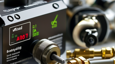
Assess Operating Conditions and Required Pressure Range

Start with the pressure the process actually experiences, not the largest number on a pipe label. Record normal pressure, startup peaks, pulsation, vacuum exposure, and possible blocked-line events. Confirm whether readings must be gauge, absolute, or differential. These are not interchangeable. Small details matter.

The U.S. Department of Energy’s Improving Compressed Air System Performance sourcebook notes that raising compressor discharge pressure by 2 psi can increase energy use by about 1% at full capacity. That figure is a useful reminder: pressure is an operating variable, not just a sensor specification.

For a compressed-air line near 100 psig, for example, choose a range that captures routine readings with useful resolution while tolerating credible spikes. Do not treat proof pressure as a normal measurement range. Not always.

Then check temperature, vibration, moisture, and the process medium at the sensing point. A hot pipe or a sharp pressure pulse can matter more than a tidy datasheet suggests. Compare total accuracy across the expected temperature range, including calibration uncertainty and installation effects. If the process has fast transients, verify response time; a stable display may simply be missing the peaks. Leave room for real operating variation, but avoid oversizing without reason. The right margin depends on the process, and that part deserves a second look.

Compare Sensor Technologies and Wetted Materials

A high-pressure sensor should be selected by both its sensing method and the materials touching the process fluid. Piezoresistive silicon designs can provide strong sensitivity in compact packages, while thin-film strain-gauge sensors use a metal diaphragm and suit many demanding pressure measurements. For rapid pressure pulses, check response time and overload limits, not just the stated pressure range. No technology wins everywhere.

Wetted materials include the pressure port, diaphragm, and any seals exposed to the fluid. 316L stainless steel is common, but it may not withstand every chloride concentration or temperature. Nickel alloys can offer better resistance in some corrosive services; confirm compatibility against the actual fluid and operating conditions. Ceramic diaphragms resist certain chemicals, yet their suitability depends on pressure, impact risk, and the sensor design. Small details matter.

Match the sensor’s range to normal operating pressure and expected spikes, then review temperature effects, vibration, and calibration requirements. Ask whether an isolation diaphragm or fill fluid separates the sensing element from the process. That detail can affect response and compatibility. A datasheet may look reassuring, but real installations include cleaning agents, temperature swings, and pressure cycling. I would verify those conditions with the sensor supplier and, where possible, test the chosen materials against the actual process fluid.

How to Choose High Pressure Sensors for Your Application? - Compare Sensor Technologies and Wetted Materials

Use this comparison as a starting point for shortlisting sensor designs. Pressure capability, accuracy, temperature limits, and compatibility depend on the complete sensor construction and should be confirmed against the application requirements.

Pressure Sensor Technology Comparison

Sensor Technology How It Measures Pressure Typical Strengths Selection Considerations Common Wetted Construction Typical Application Fit
Bonded foil strain gauge Pressure deflects a metal diaphragm; bonded resistive gauges change resistance as the diaphragm strains. Established technology; suitable for rugged industrial designs and a wide range of pressure spans, including high-pressure configurations. Temperature compensation, gauge bonding, diaphragm fatigue, and overload performance are design-dependent. Check long-term stability and cyclic-pressure ratings. Metal diaphragm and pressure port, commonly stainless steel or a corrosion-resistant alloy selected for the medium. Hydraulic systems, test equipment, and general industrial pressure measurement.
Thin-film strain gauge Resistive sensing elements are deposited directly onto a metal diaphragm, which strains under applied pressure. Compact construction with no bonded foil gauge; often selected for robust, dynamic, and high-pressure measurement. Available range, accuracy, temperature behavior, and fatigue life vary by diaphragm geometry and manufacturing process. Verify the rated pressure and proof pressure separately. Typically a metal diaphragm and port; stainless steels and nickel-based alloys are common options. High-pressure hydraulic circuits, pressure testing, and demanding industrial service.
Silicon piezoresistive with isolation diaphragm A silicon sensing element detects pressure transferred through a fill fluid from an isolation diaphragm. High sensitivity and compact electronics; useful where a small sensor package or strong low-pressure resolution is needed. The isolation diaphragm, fill fluid, and seals determine media compatibility. Temperature effects and overload limits require careful review, especially at the upper end of the pressure range. Wetted isolation diaphragm and port are commonly metal; the silicon die is usually separated from the process medium by fill fluid. Industrial transmitters and applications needing a compact, sensitive measurement with process isolation.
Capacitive diaphragm Pressure changes the spacing or geometry between conductive surfaces, changing capacitance. Can provide high sensitivity and low measurement drift in suitable designs; available in metal-diaphragm and ceramic-based constructions. High-pressure capability depends strongly on diaphragm support and mechanical design. Consider vibration, overload, signal conditioning, and process isolation requirements. May use a metal diaphragm or a ceramic measuring element; ports and seals must also be compatible with the process fluid. Applications prioritizing sensitivity or stability where a pressure-rated design is available for the required range.
Resonant sensing Pressure-induced strain changes the resonant frequency of a sensing element, which is measured electronically. Frequency output can support precise measurement and good long-term stability in carefully engineered instruments. Often more complex and costly than basic strain-gauge designs. Confirm pressure range, vibration sensitivity, temperature compensation, and response time for the specific model. Usually uses a pressure-isolating metal diaphragm and process port; the resonant element may not contact the medium. Precision process measurement and applications where stability or repeatability is a priority.

Wetted Material Comparison

Wetted Material Typical Advantages Important Limitations Common Selection Context
316L stainless steel Widely available, generally good corrosion resistance in many industrial and aqueous services, and readily fabricated. Chlorides can cause pitting or crevice corrosion; temperature, concentration, and stagnant conditions affect performance. General-purpose process fluids and hydraulic or pneumatic service when the specific medium is compatible.
17-4PH stainless steel High strength and hardness can support compact pressure-bearing parts. Corrosion resistance depends on heat treatment and environment; do not assume it is interchangeable with 316L in chloride service. High-strength ports or components where mechanical properties are important and the process chemistry has been checked.
Hastelloy C-276 Nickel-based alloy used in a range of demanding corrosive environments. Compatibility is not universal; the exact chemical, concentration, temperature, and contaminant profile must be evaluated. Aggressive chemical service where standard stainless steels are unsuitable and compatibility has been verified.
Titanium, Grade 2 Good resistance to seawater and many chloride-containing environments under appropriate conditions. Not suitable for every acid or reducing environment; assess temperature, crevices, and hydrogen-related risks for the specific service. Selected marine, seawater, and chloride applications after chemistry and pressure design review.
Inconel 718 High strength and useful performance in elevated-temperature mechanical applications. High strength does not guarantee compatibility with a particular process fluid; verify corrosion behavior and the finished component condition. Pressure-bearing components requiring high mechanical strength or elevated-temperature capability.
Alumina ceramic Resists many chemicals and provides electrical insulation; useful in some ceramic sensing constructions. Ceramic is brittle and can be sensitive to impact, mounting stress, and thermal shock. Seals and joints may set the practical compatibility limit. Applications where ceramic compatibility or electrical insulation is beneficial and mechanical handling conditions are suitable.

Selection note: “Wetted material” includes every surface exposed to the process medium, such as the diaphragm, pressure port, seals, and any isolation fluid interface. Confirm chemical compatibility at the actual concentration and temperature, as well as maximum operating pressure, proof and burst ratings, pressure cycling, temperature range, accuracy, and required output signal.

Evaluate Accuracy, Output Signals, and Response Time

Choosing a high-pressure sensor starts with the operating range, but the accuracy details deserve a closer look. Accuracy may be specified as a percentage of full scale or of the reading; these values behave differently at low pressures. For example, a 0–1,000 bar sensor with ±1% full-scale accuracy may have an error of ±10 bar at a 100 bar reading. Check whether the specification includes temperature effects, hysteresis, and long-term drift. Read the calibration sheet.

Match the output signal to the control system and wiring. Voltage outputs can be suitable for short, quiet connections, while current-loop signals often handle long cables and electrical noise better. Confirm the receiver’s input range, supply voltage, and resolution; an incompatible range can hide useful measurement detail. Digital outputs may provide diagnostics, but only help when the controller can use them.

Response time matters when pressure changes quickly, such as during a pump start or valve closure. Compare the sensor’s response specification with the speed of the process, and check whether internal damping or software filtering adds delay. A very fast sensor is not always better; it may capture pressure spikes that the application does not need to react to. It is easy to overvalue one headline number. Test the chosen setup under realistic pressure cycles, then review whether its readings support the actual control decisions.

Check Safety Ratings, Certifications, and Installation Needs

How to Choose High Pressure Sensors for Your Application?

A sensor’s pressure range is only part of the decision. Check its maximum working pressure, proof pressure, and burst pressure against normal operation and credible pressure spikes. A system that usually runs at 800 bar may experience sharp surges during pump startup. Leaving no margin can shorten sensor life or create a safety risk. Also confirm that wetted materials suit the process fluid and operating temperature.

Review safety ratings and certifications for the actual installation environment. Requirements may differ between industrial sites, mobile equipment, and hazardous locations. Verify what each certification covers; an enclosure rating does not confirm pressure suitability. Check the sensor’s electrical protection, connector type, and approved pressure connections.

Installation details matter. Vibration, pulsation, poor alignment, or overtightened fittings can cause leaks or unreliable readings. A pressure snubber or isolation valve may help, but only if it suits the process and does not compromise response time. It is easy to assume a standard fitting will fit. That assumption deserves a second check.

Tips: Compare the sensor’s specifications with real operating conditions, not just the nominal pressure. Confirm thread type, sealing method, and cable clearance before installation. Keep the certification documents and calibration record accessible. A careful review takes minutes; correcting a poor installation may take much longer.